
Build: Sirius Rocketry S.S. Cestris
Looks like all the parts are here!
The rocket construction phase is complete!
|
|
|||
|
Build: Sirius Rocketry S.S. Cestris |
|||
|
|
|
||
|
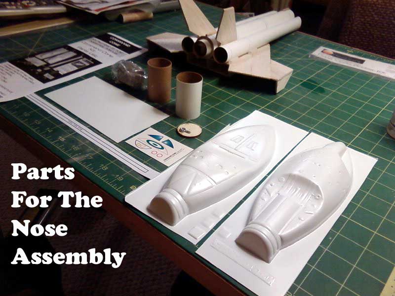
Looks like all the parts are here! |
|||
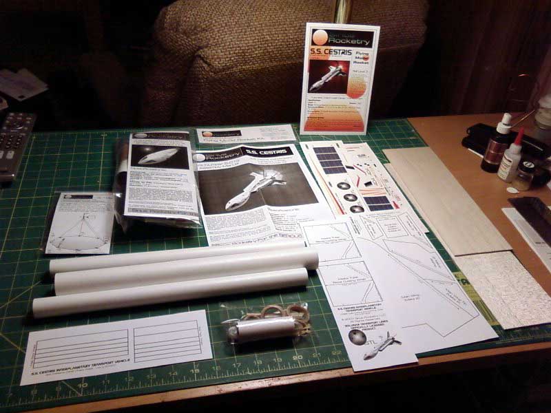
| DAY ONE | The kit arrived, in a good sized box, by Priority Mail. It was packed well and I could find no damage to the kit. I opened the package and laid out all the contents as seen in the photo. All the small parts are in one bag, as were the parachute and the nose cone kit. There are two sheets of balsa, 3 body tubes, fin and intake patterns, self adhesive body wraps, 4 sheets of water slide decals and a 12 page instruction manual. I sat back in my recliner and read the instructions which are superbly detailed. | |
|
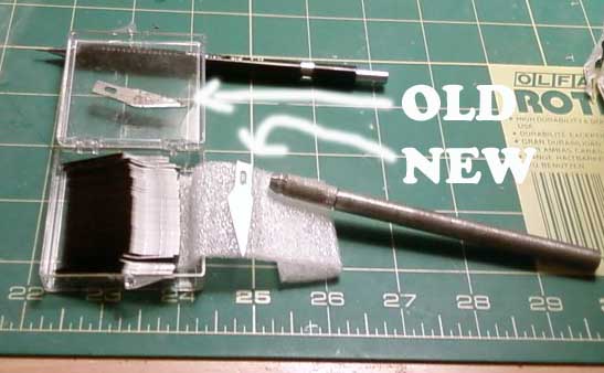
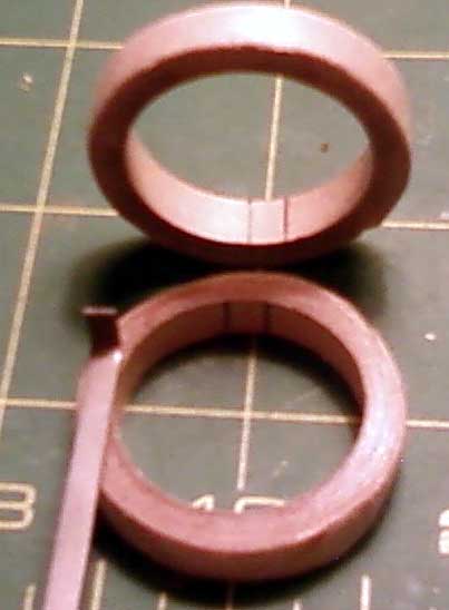
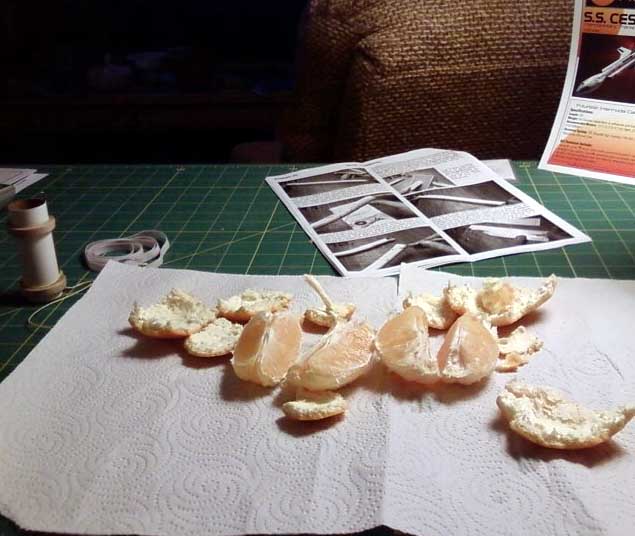
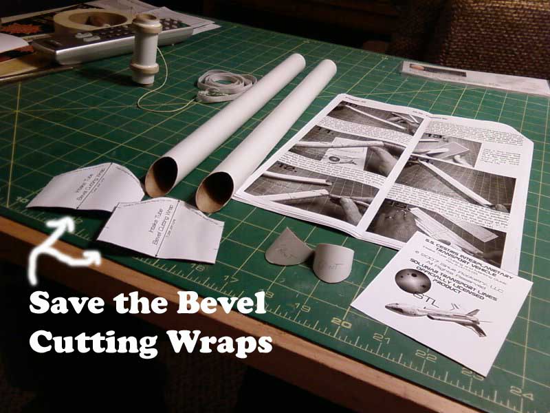
| DAY TWO | While watching the the NASA STS-122 day four coverage, I got started. The first thing in the instructions are tips. The main one was "use a new blade in your knife", so I changed my rusty, broken tipped blade, for a shiny new one. I then followed steps 1-9 and completed the motor mount assembly. I used the motor hook to draw reference lines to show where to make the notches in the the centering rings. The mount features the "Quest-like" Kevlar shock cord of which I approve. I then paused for a refreshing navel orange. Next I completed steps 10-13 where you use patterns to cut the bevels in the two T-50 intake tubes. The new sharp blade made this a snap.I carefully removed the transparent tape from the patterns so that I can save them just in case. | |
|
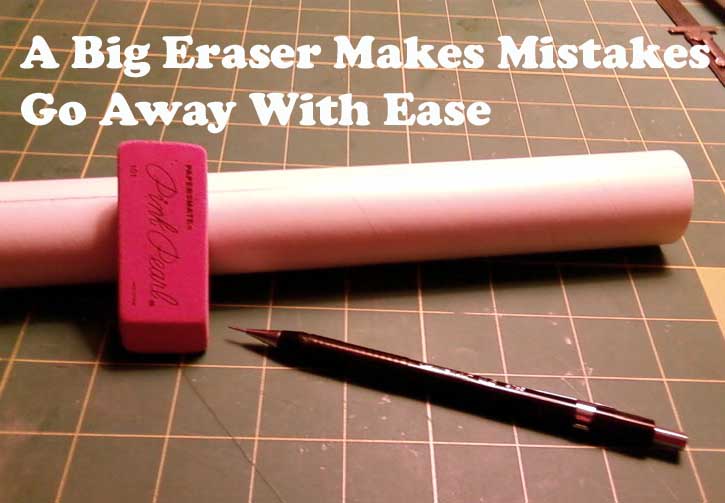
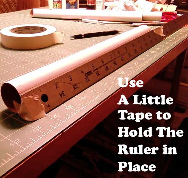
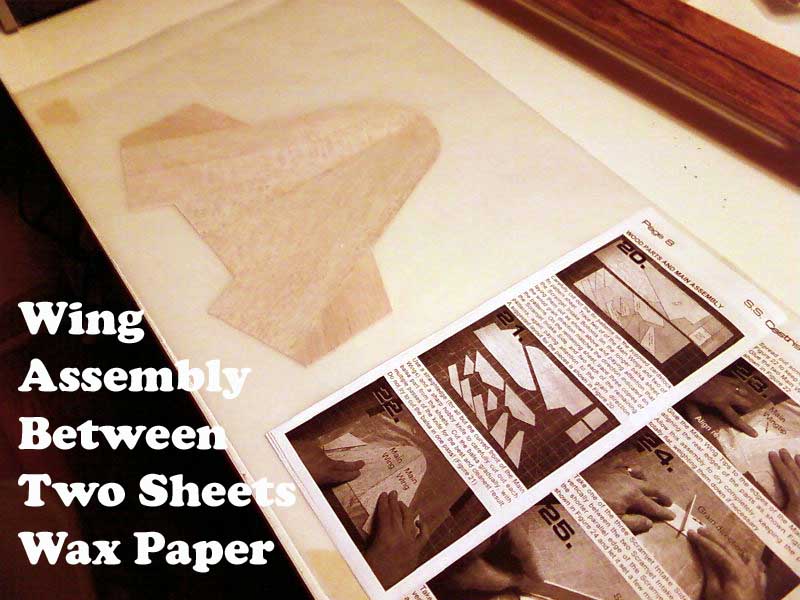
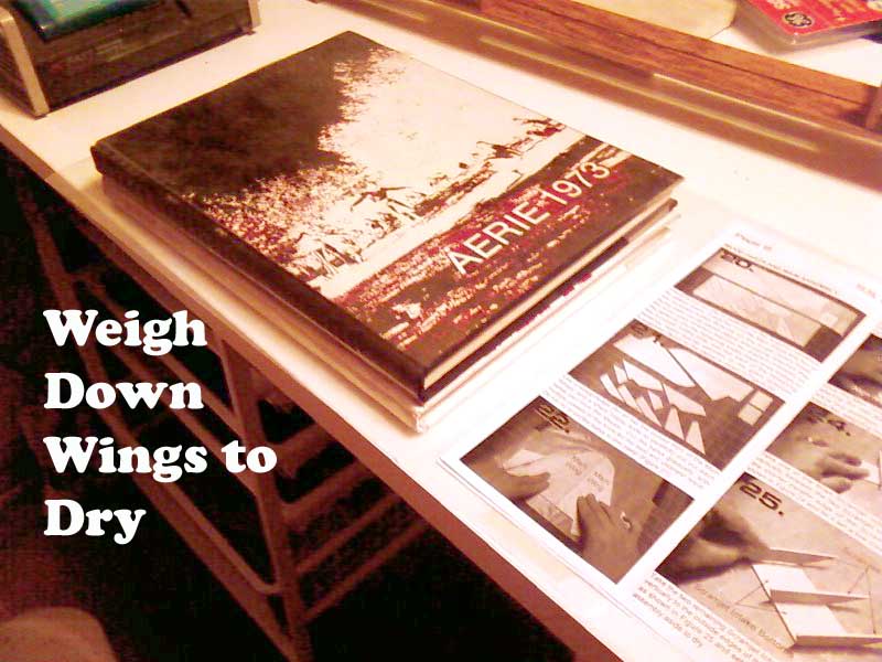
| DAY THREE | I kicked things off by sanding the bevels on the each of the intake tubes. Next I drew a line and marked the increments specified on the Main body tube. All the measurements in the instructions are in inches (no metric here). I made a couple of mistakes but they were easily erased and corrected. For an extra hand, I taped the ruler in place, even with the front end of the tube. Next up was cutting out body wrap strips on self adhesive paper and attaching them where indicated around the three tubes. When you glue the three tubes together, the next step, you hide all the joints where the strips come together (very clever). With that complete, and the joined tubes drying, it was time to cut out the balsa parts. They have a nice layout in the instructions to show where to place each of the pieces on the two sheets of balsa. The sharp blade comes in handy here. As my last step before bedtime, I glued up the Main Wings and Wingtips on some wax paper and weighted it down to dry overnight. I knew those High School Annuals were a good purchase! | |
|
|
|
|||
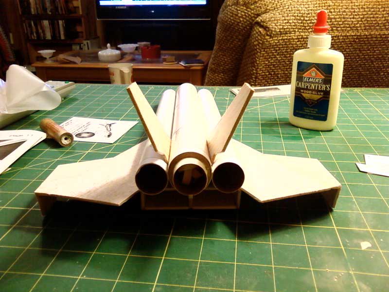
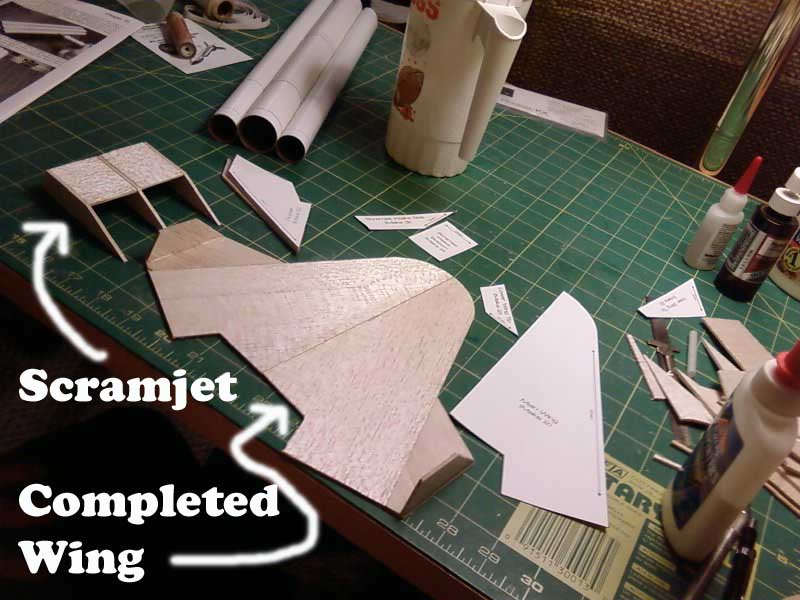
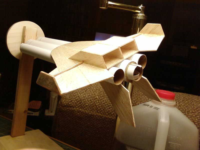
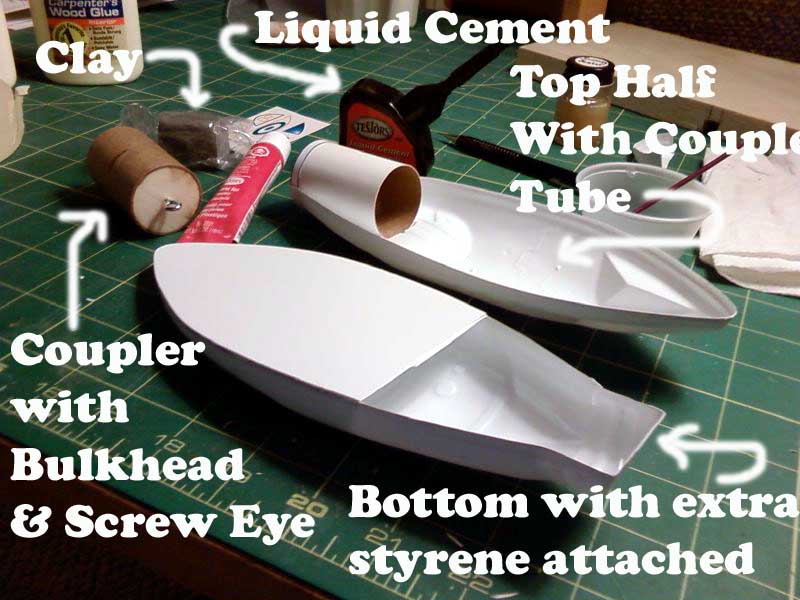
| DAY FOUR | I retrieved the wing from the wax paper and glued the wing tips on with medium CA. Next I completed the Scramjet assembly with the same adhesive. The next step was gluing the Scramjet to the wing and then the Wing assembly to the flat side of the body tubes. I then used wood glue to insert the motor tube. Per the instructions I sanded a bevel on the root edges of the two Rudders and then glued them in place with CA. Next I beveled one end of each of the pre-cut dowels and used CA to attach them where indicated. The launch lug needed to be cut into two equal one inch pieces which I used my miter box and saw to accomplish. After some clean-up sanding I used CA to glue them into place. I then added some glue fillets to the main body assembly and set it aside to dry. I then opened the Command Cone package and laid out the parts. It comes with two styrene nose halves, a square piece of styrene, 2" BT-55 and coupler, clay noseweight, plywood bulkhead, decals, screw eye and an illustrated 6 page instruction sheet. I read the instruction booklet completely and then cut out the top-half of the Command Cone per instructions 1-3. I need to purchase some liquid plastic cement (not the tube type) but the kind you apply with the brush like nail polish. I then typed this and went to bed. |
|
|
|
|
|||
| DAY FIVE | `I went to Hobby Lobby and bought some Testers Liquid Cement for Plastic Models. When I got home I sanded the balsa parts and applied the first coat of sanding sealer. Next, I then used regular plastic cement to glue the BT-55 tube inside the top of the nose cone and set it aside to dry. With my sharp blade I cut away the styrene that is rear of this tube and cut out the bottom half of the nose cone. Now the liquid cement is used to glue on a sheet of styrene to give the bottom half more rigidity. I sanded the balsa parts and added another coat of sanding sealer. | |
|
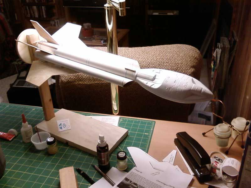
| DAY SIX | Ok, what is to be the final day for the main construction,
started with more sanding and sealer. Next I cut the excess styrene away
from the bottom nose piece. I had to sand the bottom half a little as I test
fitted the two halves together. They fit really nice and letting the liquid
cement flow into place using capillary action worked great as the
instructions stated. I completed the coupler tube with the bulkhead and
screw eye and then sanded and added the final coat of sanding sealer. After
a few hours the nose cone was adhered nicely and I cut away the final
unnecessary styrene piece and sanded the edges so the cone would fit nicely
against the rocket body tube. I then packed all the clay into the bottom
front portion of the nose. I added a little paper with some Elmer's glue to
hopefully help hold the clay in place. It then glued the nose coupler into
place. The rocket construction phase is complete! |
|
|
|
|
|||